Revision Control  ·  10 Structural Sheets

Two drawings.
Three months.
A different structure.

17% of the April drawing layout vanished in July. Here is what our audit uncovered.

Present in April, removed in July Introduced in July
Scroll
105
members reviewedmark by mark
60
marked REJECTdo not approve for construction
17%
of layout vanishedvector diff between submittals
5
business daysfrom DWG submittal to audit report

01 Sheet S-1 · Foundation Plan

Drag to compare. Same project, three months later.

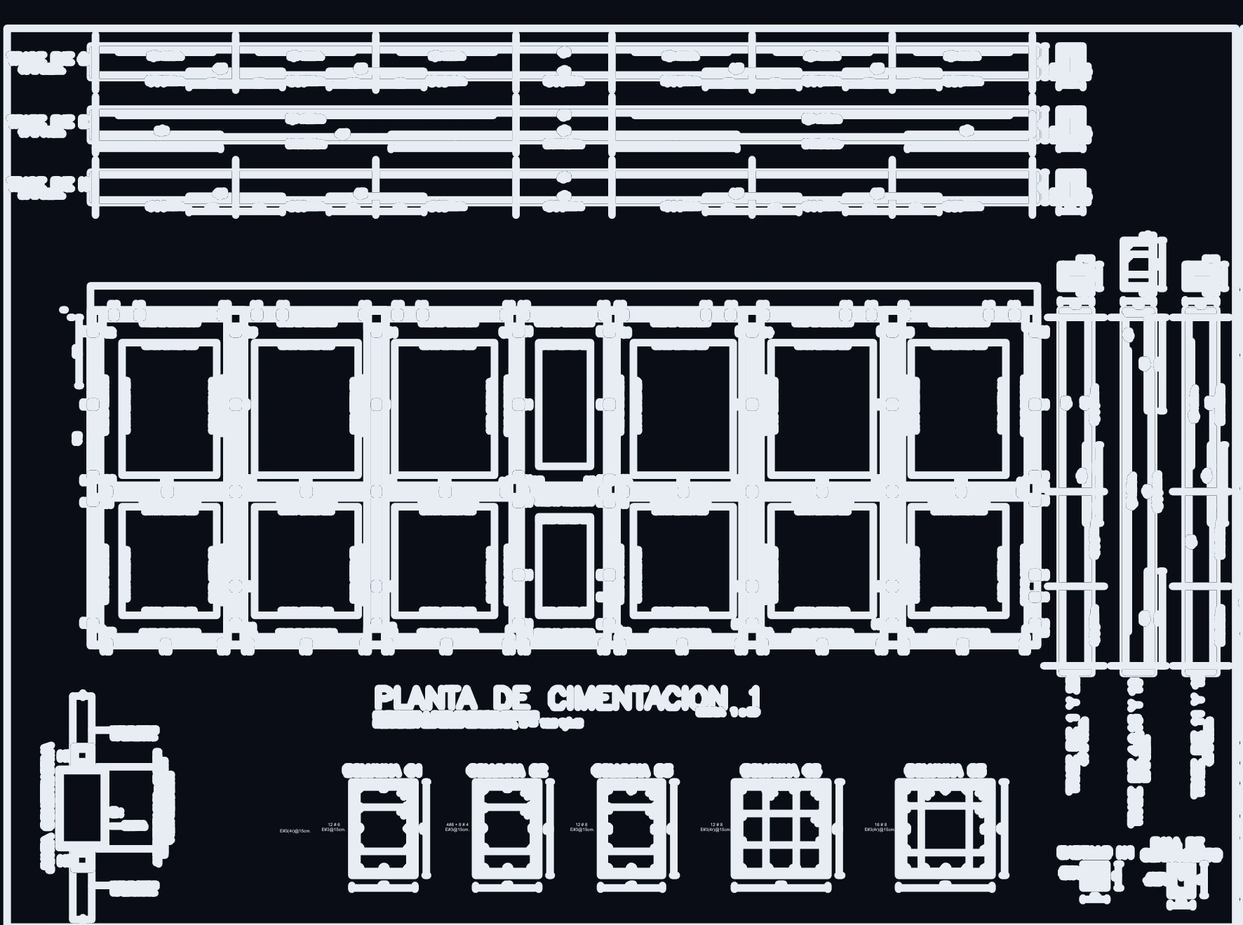
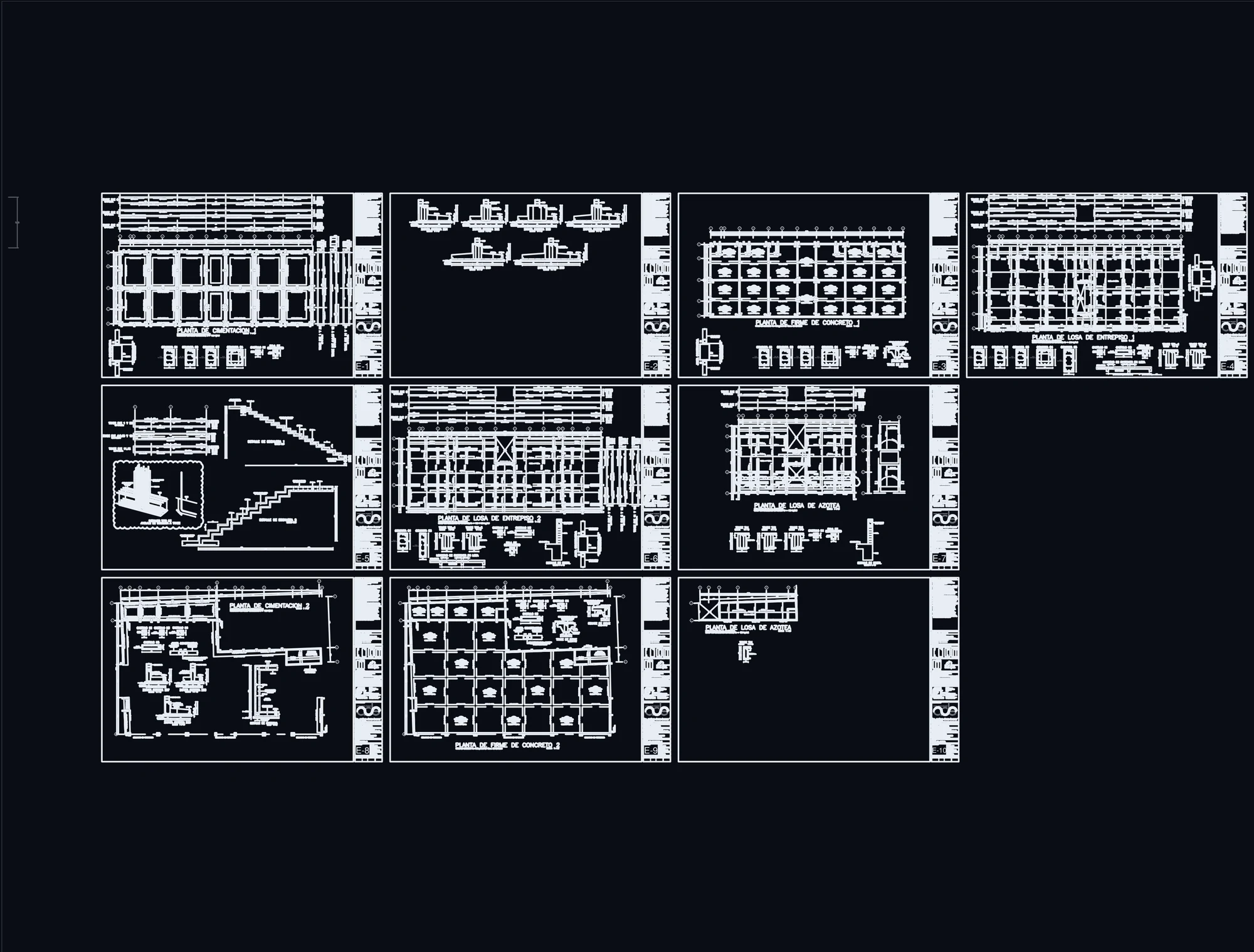
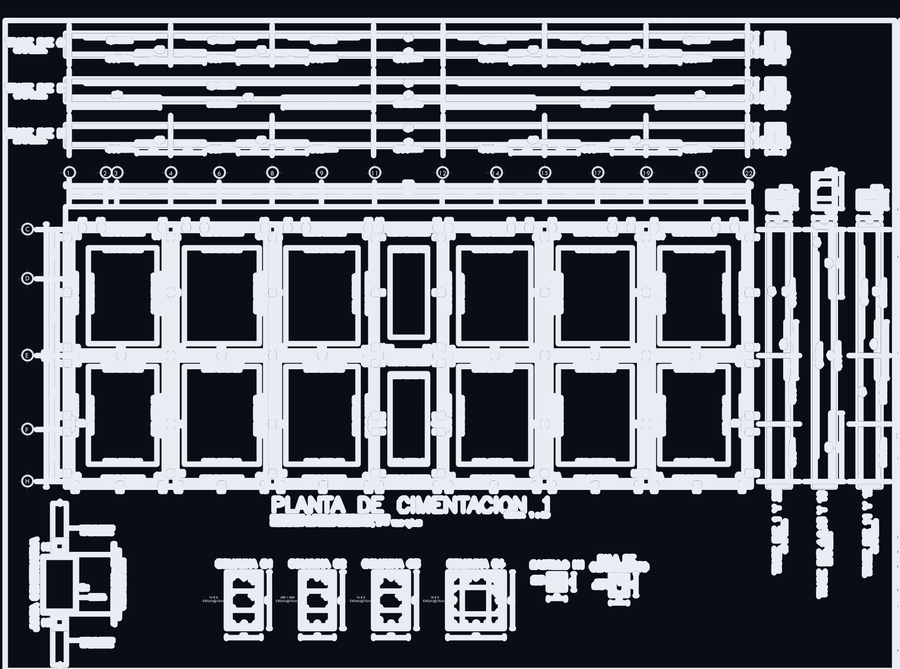
Planta de cimentación, emisión de abril
Planta de cimentación, emisión de julio
Apr 17
Jul 29

Exact geometry from original CAD submittals, exported to PDF and rendered without retouching. Column grid alignment remains identical; what changed is rebar detailing, member marks, and callouts.

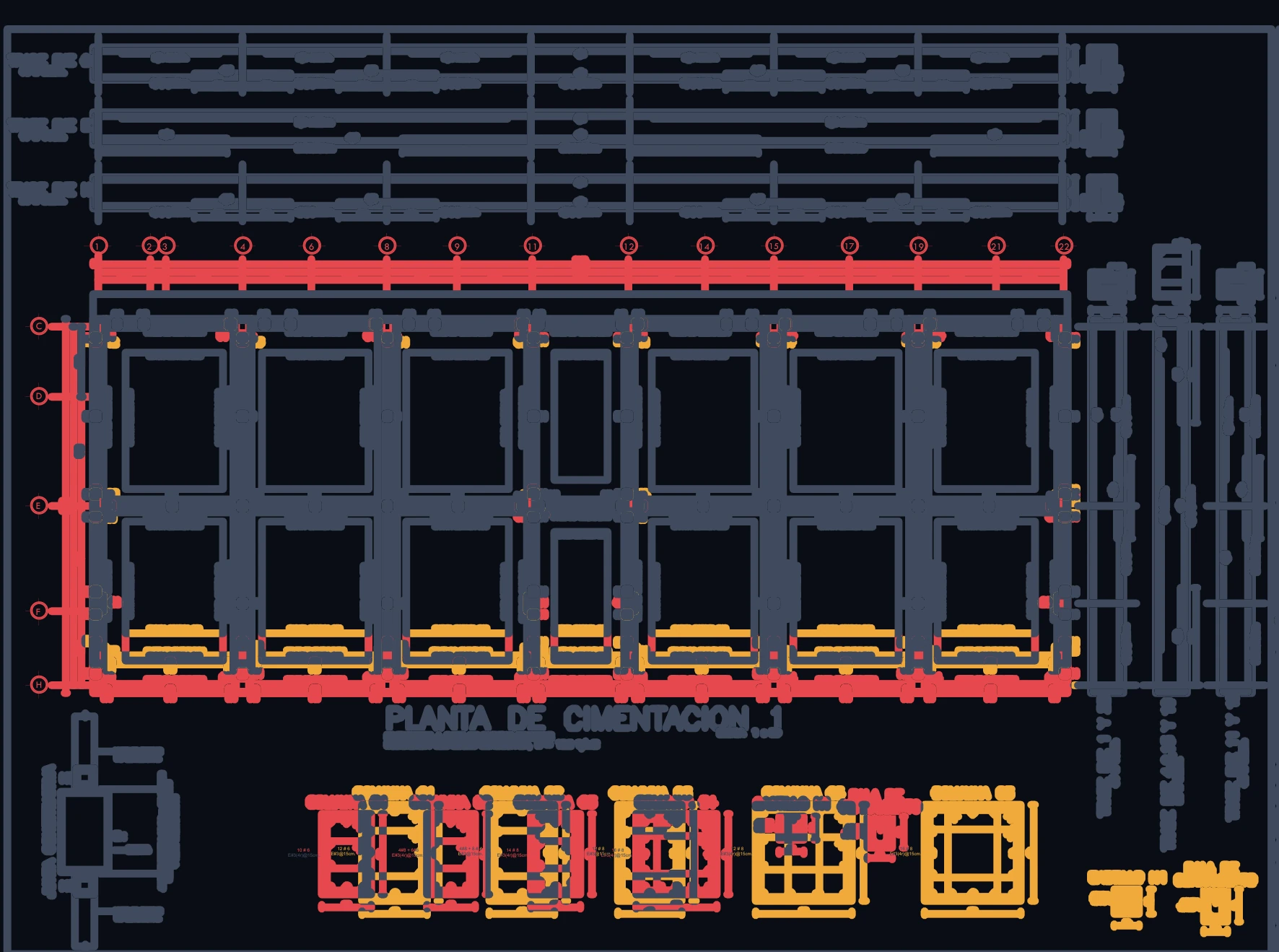
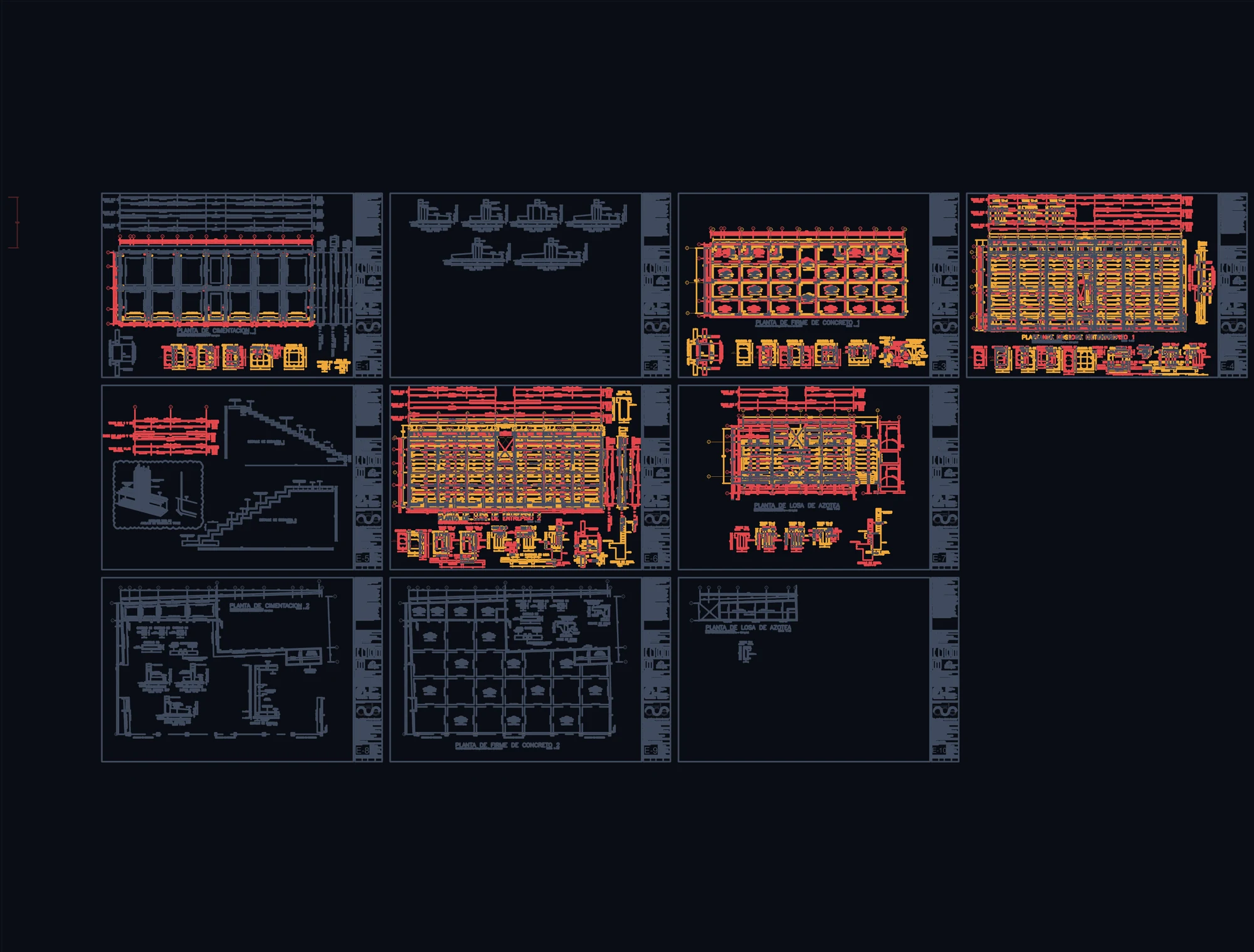
Diferencia de trazo entre las dos emisiones: rojo lo eliminado, ámbar lo nuevo

Fig. 01 — Vector Layout Diff · April ⇄ July

Gray: unchanged geometry. Red: present in April, vanished in July. Amber: newly introduced in July. The entire perimeter grade-beam schedule and footing reinforcement were rewritten.

02 Engineering Finding

This is not a cosmetic redraft.
Do not approve for construction

Fundamental shift in rebar criteria, renumbered beam schedules, aggressive reduction of tie-columns, and missing elevation callouts. This is a preliminary design redesign, not an issued-for-construction set.

03 Audit Status

105 member lines. Only one passed clean.

Member Mark Schedule54 elements
54
Global Reinforcement Details38 line items
38
Submittal Readiness Checklist13 milestones
13
REJECT — 60REVISE — 44APPROVED — 1

04 Reinforcement Deltas

The steel didn't vanish from the building.
It vanished from the drawings.

← fewer in Julymore in July →

Frequency of rebar callouts, April vs. July. Square-root scale applied so that −56 remains legible alongside +403.

05 Tie-Columns K1

0
0
−66 %

Could be intentional structural optimization—or load-bearing wall load paths that are no longer resolved. The determining factor is the calculation report, and the report was never provided with the drawings.

06 Finite Element Verification

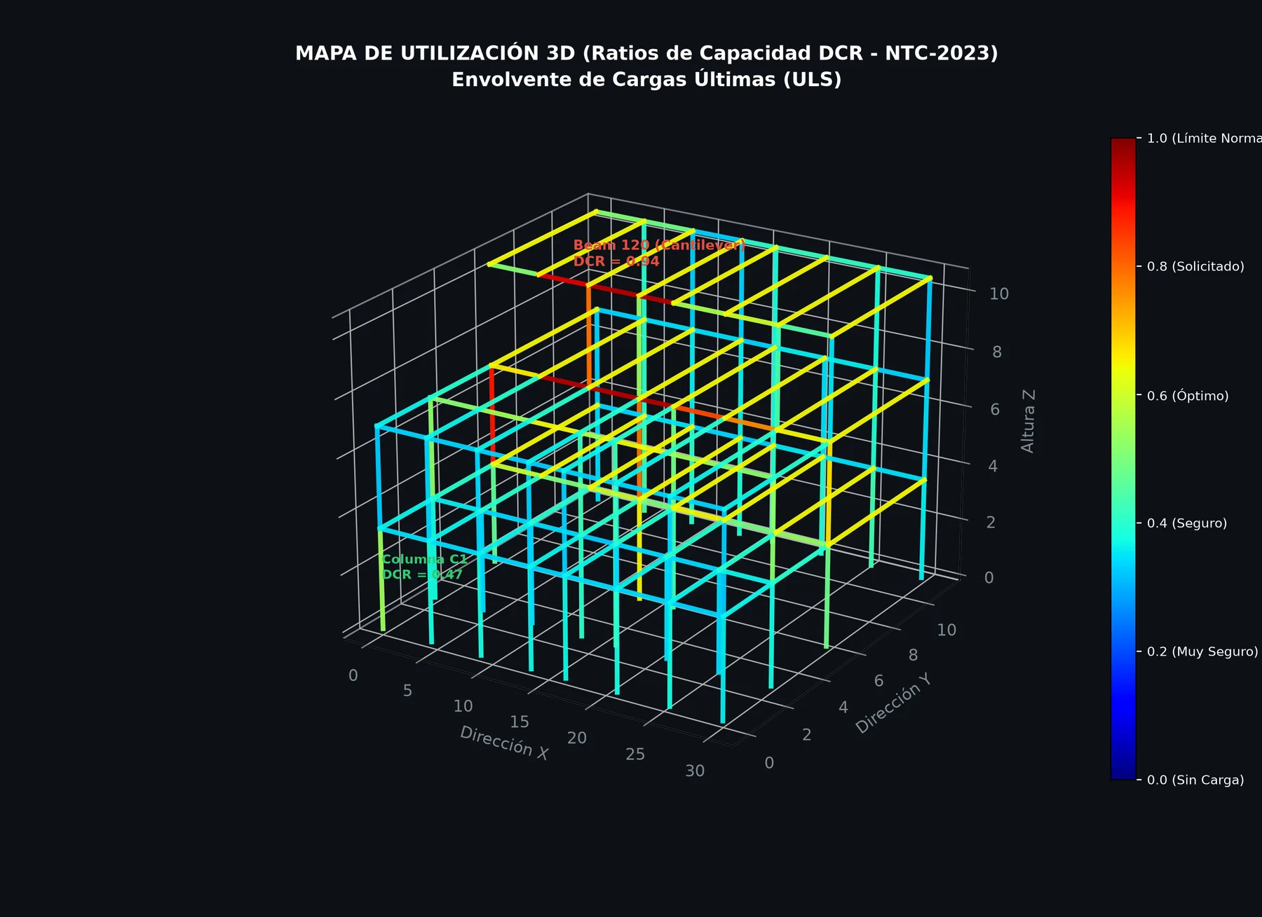
Mapa de utilización 3D con ratios de capacidad DCR bajo NTC-2023

Fig. 02 — Utilization Ratio Map · DCR

Cantilever beam B120 reaches DCR = 0.94. At that stress level, expanding tie spacing from 6" to 8" (15 to 20 cm) is no longer cosmetic.
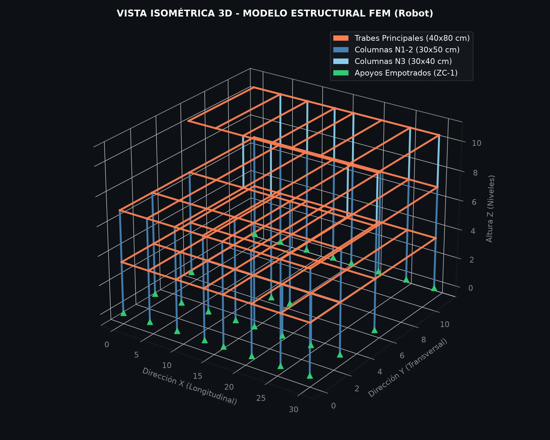
Vista isométrica del modelo estructural FEM

Fig. 03 — 3D FEA Model

40×80 cm beams, 30×50 and 30×40 cm columns, fixed boundary conditions on continuous strip footings.
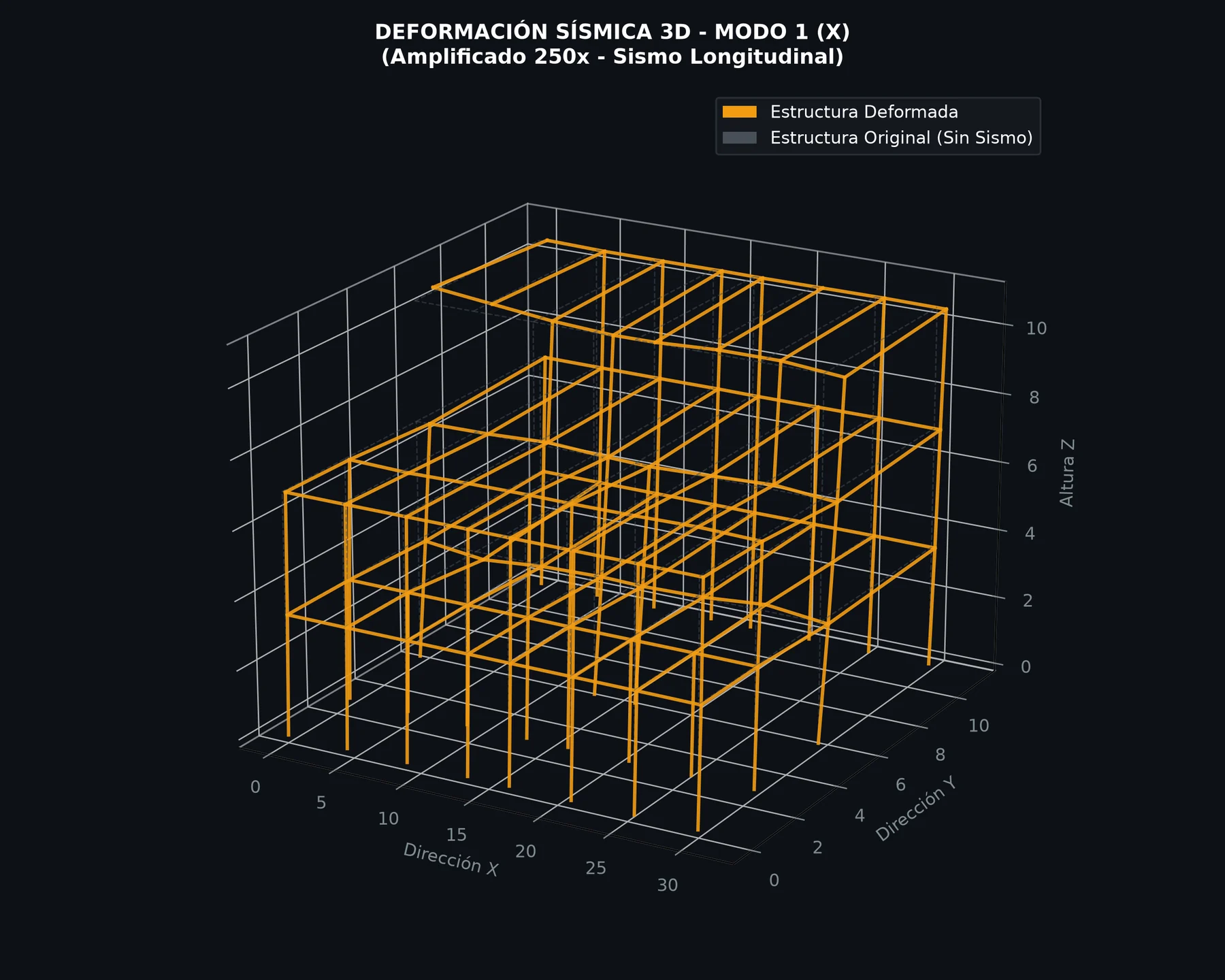
Deformada sísmica tridimensional del modo fundamental

Fig. 04 — 3D Mode Shape

Determines which tie-columns and shear walls actively participate in lateral load transfer.
Δ roof0.00 cm
Drift0.00055
Code Limit0.012
Amplified 250×

Fig. 05 — Fundamental Mode in X Direction · Dynamic View

Actual lateral displacements under static seismic analysis (T = 475 yrs): 0.10, 0.21, and 0.42 cm per story. Inter-story drift computes to 0.00055 against a code ceiling of 0.012 — 22 times below permissible threshold. The structure itself is not overstressed; the core risk is blueprint traceability.

07 Prior to Concrete Pour

Six critical items to resolve.

  1. Reconcile stirrup spacing criteria (#4@10→@20 and #3@15→@20) against calculation reports and code.

  2. Issue a signed engineering equivalence schedule for beam marks TA/TE → T1/T2.

  3. Provide structural justification for the reduction of K1 tie-columns and shear wall load paths.

  4. Restore top-of-slab elevation callouts (+3.72 / +7.32 / +10.92 m) and missing section callouts.

  5. Audit the anomalous spike in callout 2#4—jumping from 9 to 412 annotations.

  6. Issue a clean Construction Set purged of revision comparison/XREF layers.

A drawing set isn't approved
just because it looks good.

8 audit pages, 4 source CSV logs, and one formal certification sheet.

Request an A/B Structural Review

Submit both DWG revisions. In 5 business days, we deliver an authoritative verdict on construction readiness.

WhatsApp +52 56 2361 0806  ·  View all services →