When the center of mass diverges from the center of rigidity, seismic force doesn't just push: it twists. Building codes limit this offset to 10% of plan dimension. Two of the structure's four calculated eccentricities violated this ceiling—one by nearly triple.
BeforeAfterCode Limit
Eccentricities in meters measured on the numerical model. The code limit is 0.10 × plan dimension per axis. Resolution was achieved by adding strategic shear walls rather than oversized sections: four walls in total across both building wings.
02 Structural Walls
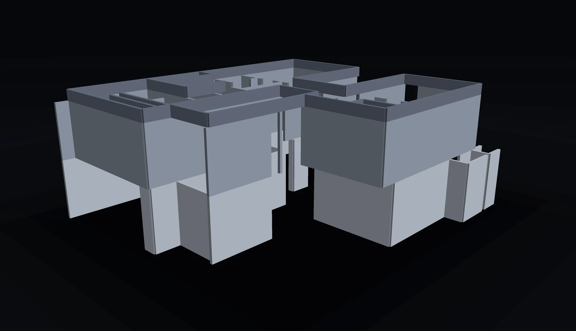
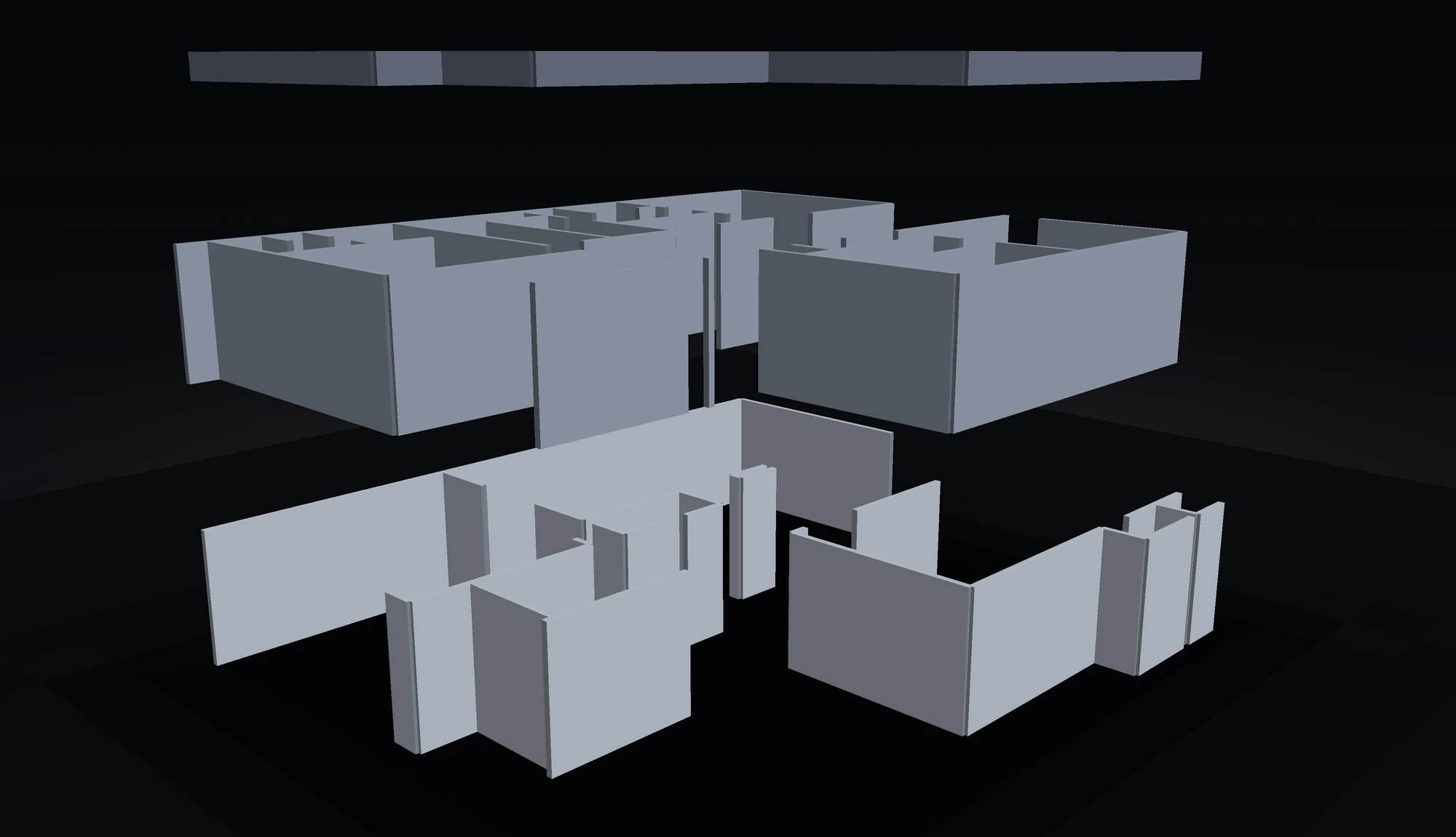
88 masonry walls, mapped directly from the FEA model.
Fig. 01 — Exploded Axonometric View by Story
Three distinct elevation levels separated for clarity: 27 walls on ground floor, 36 on upper floor, and 25 parapets. Each wall is rendered to its true 15 cm 3D volume, not a symbolic line.
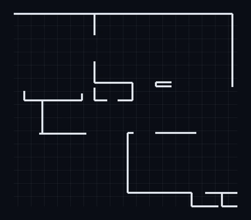
Fig. 02 — Ground Floor · 27 Walls
Base elevation at +0.10 m, top bond beam at +3.20 m. 15 cm walls with 15×15 cm tie-columns.
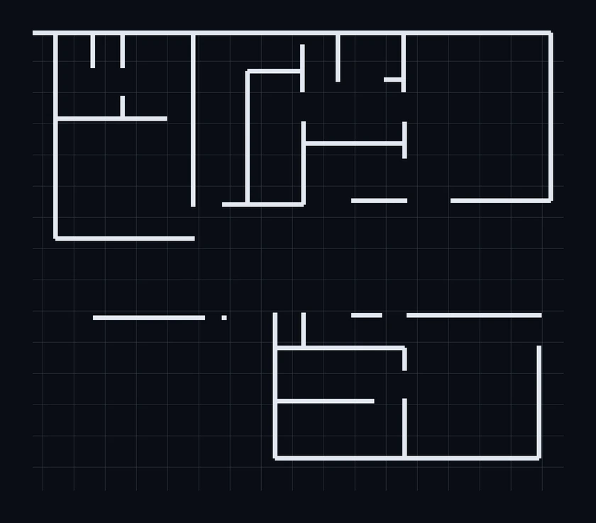
Fig. 03 — Upper Floor · 36 Walls
From +3.20 m to +6.10 m. Identical framing perspective as ground floor for direct overlay comparison.
These are not screenshots. 239 nodes and 15 cm solid panels are parsed from the calculation model, projected to planar coordinates, and classified by elevation range. 1-meter background grid.
03 Structural Regularity Criteria
Six criteria met. The seventh is formally penalized.
An irregular structural layout is not prohibited: it is penalized. The geometric re-entrant corners exceed 20%, so the seismic behavior factor is penalized with α = 0.8, elevating design seismic demand accordingly.
✓
Plan symmetry of mass and stiffness
Complies
✓
Height to narrowest plan dimension ≤ 2.5
0.42
✓
Aspect ratio (length / width) ≤ 2.5
Complies
!
Re-entrant corners ≤ 20% of floor plan
irregular · α = 0.8
✓
Rigid floor diaphragm at each level
losa V+B 25 cm
✓
Diaphragm slab openings ≤ 20%
15.9 %
✓
Story mass variation within permissible limits
Complies
04 Building Code, Article by Article
Every code requirement with its verified metric.
Our calculation reports don't say «complies with building code». They cite the exact article, what is required, and what was engineered.
Art. 223Engineered foundation; no bearing on uncompacted fill or topsoilzapata corrida B = 0.95 m
Art. 224Minimum foundation embedment depth 60 cmDf = 1.20 m
Art. 228Factored load combinations and safety factorFS > 2.0
Art. 251Minimum tie-column cross-section 15 cm15 × 15 cm
Additionally: CFE MDOC 2015 for seismic and wind actions, and NTC-Masonry 2023 for confinement detailing. Tie-column spacing on parapets complied with the special provision allowing spacing s ≤ 4.0 m when height H ≤ 1.5 m.
05 Seismic Design Criteria
Low seismic hazard does not mean zero seismic hazard.
Zona B del Golfo, margen pasivo, suelo firme. La aceleración del terreno es modesta — pero la mampostería confinada tiene un factor de comportamiento de apenas Q = 2, así que la fuerza de diseño no baja tanto como parecería.
And with the irregularity penalty factor, lateral design demand increases proportionally.
Occupancy category
B2
Structural system
1 muros
Seismic zone
B
Subsoil type
firme Vs30 > 360
a₀ PRODISIS
28.91 cm/s²
Ductility behavior Q
Q = 2
Concrete f'c
f'c 250 kg/cm²
Rebar steel fy
fy 4200 kg/cm²
Masonry f*m
f*m 15 kg/cm²
Floor slab system
V+B 25 cm
Roof Dead Load
508 kg/m²
Max Live Load
190 kg/m²
06 Modal Response Spectrum Analysis
The structure does not oscillate identically in both axes.
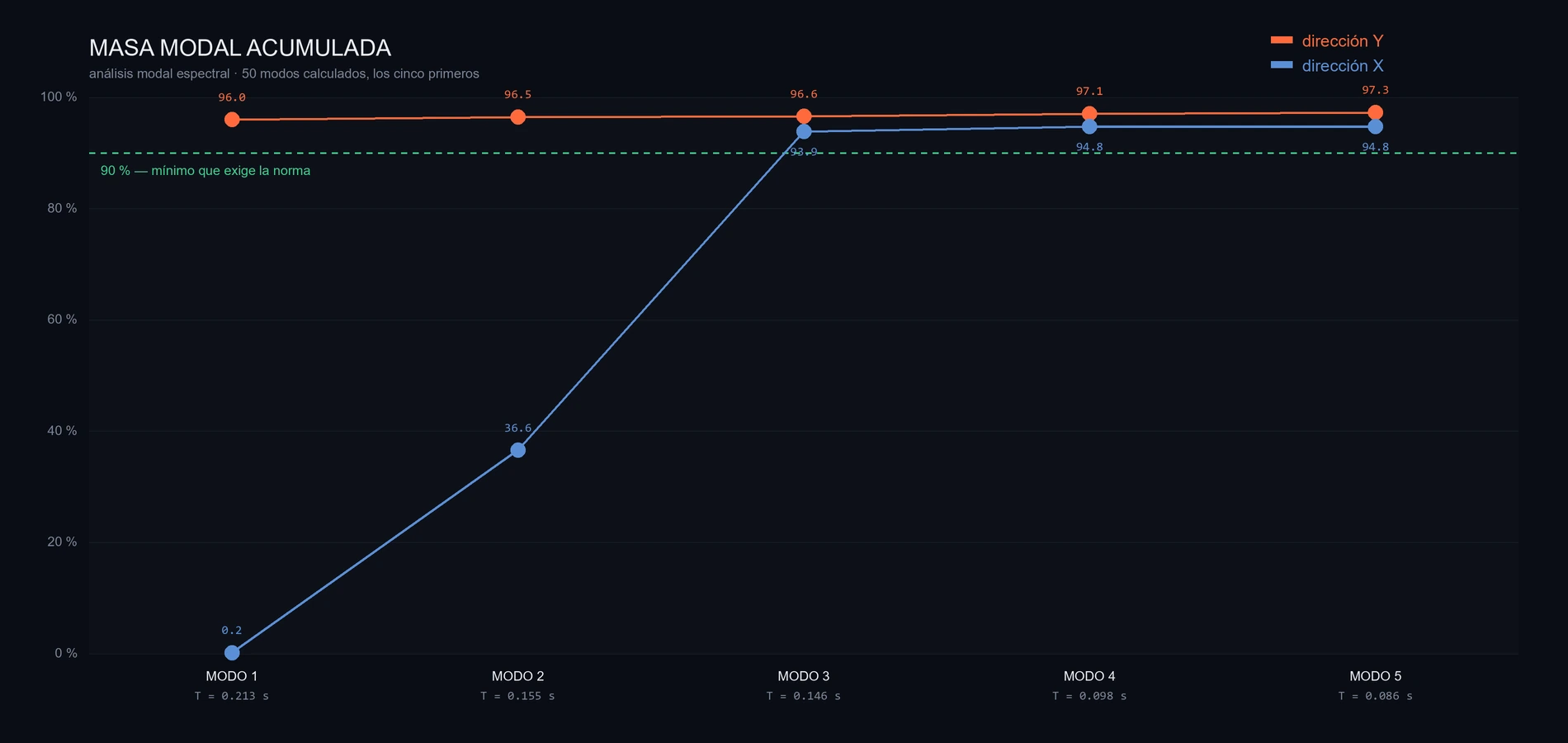
El primer modo, con periodo de 0.213 s, moviliza el 96 % de la masa en Y y apenas el 0.2 % en X. En X hacen falta tres modos para pasar el 90 % que exige la norma. Esa asimetría es la misma que aparecía en la excentricidad — y por eso los muros que se añadieron fueron en esa dirección.
Fig. 04 — Cumulative Modal Mass · Response Spectrum Analysis
50 dynamic modes were computed; the chart displays the first five fundamental modes. Cumulative modal mass reaches 100% in both principal axes, far exceeding the 90% code threshold.
Max story drift X
0.0030 rad
Max story drift Y
0.0030 rad
Code drift limit
0.0060 rad
Modes computed
50
Modal mass X
100 %
Modal mass Y
100 %
La deriva de entrepiso queda en la mitad del límite en ambas direcciones. Método: modal espectral, con verificación estática por tratarse de un Grupo B2.
Two critical adjustments mandated by the FEA model.
El cortante dinámico salió bajo. El espectral daba 5.27 t en X y 5.08 t en Y, contra un umbral de 7.50 t — el 70 % del estático. La norma obliga a escalar el sismo de diseño hasta ese 70 %, y así se hizo.
El peso hubo que reconciliarlo. El modelo reportaba 454.7 t y la bajada manual 412.8 t: 9.2 % de diferencia. Dentro del 10 % aceptable, pero sólo se sabe después de hacer las dos cuentas.
Dynamic shear Vx
5.27 ton
Dynamic shear Vy
5.08 ton
70% Static V threshold
7.50 ton
FEA model weight
454.7 ton
Manual take-off weight
412.8 ton
Difference
9.2 %
07 Gravity & Dead Loads
Half a metric ton per square meter on the roof.
In load-bearing masonry, live load is rarely decisive: dead load governs. The mortar topping, slope fill, and roof finishes weigh nearly as much as the slab itself—and that mass is what the seismic acceleration accelerates laterally.
Dead LoadMax Live Load
Values in kg/m². Roof live load reflects an inaccessible roof deck; second floor reflects residential occupancy. Slab weights correspond to the 25 cm precast joist and block system specified in the project.
A model is built to uncover problems.
If everything passes on the first run, you probably didn't look closely enough.