Tubular Arch Canopy · 40 ft ISO Containers

Twelve-meter clear span.
Eight supports.
Six are not ours.

The engineered canopy rests atop two client-supplied shipping containers that cannot be certified. The entire engineering design revolves around that reality.

12.102m
clear span between gridlineszero interior columns
144/144
members verifiedAISC 360-16, ASD ASCE 7-16
157
connections engineeredzero exceeding 1.0 limit
0.829
highest stress ratiojoint 33, tubular CHS intersection

01 Erection Sequence

Seven erection phases. In this exact sequence.

The sequence is not optional: each stage structurally stabilizes the previous. Sheet S-12 mandates it and prohibits alteration without engineering sign-off.

Etapa 01 / 07
Terreno y cajas existentes

02 The Typical Arch Truss

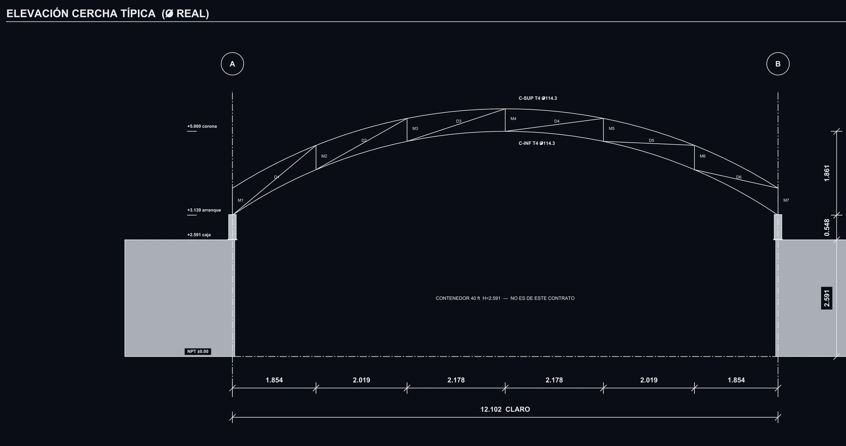
A true constant-radius arch, not a segmented polygonal.

Elevación de la cercha típica con cotas de claro, arranque, corona y flecha

Fig. 01 — Typical Truss Elevation · Sheet S-04

Two concentric Ø114.3 mm round HSS chords curved to constant radius, with Ø60.3 mm web lacing. Three trusses are identical; the fourth differs as it extends down to ground grade.
Gridline clear span
12.102 m
Arch springline
+3.139 m
Arch crown
+5.000 m
Rise / Sagitta
1.861 m
Top chord radius
11.268 m
Container stub post
0.548 m

Se corta a radio real y se preensambla en piso. La nota de fabricación de la lámina es explícita: «las diagonales no se cortan aún; su ángulo contra el cordón queda bajo el mínimo de 30° para junta CHS directa».

03 Mounting to Existing Containers

Our support post is 0.548 m. The rest is client-supplied.

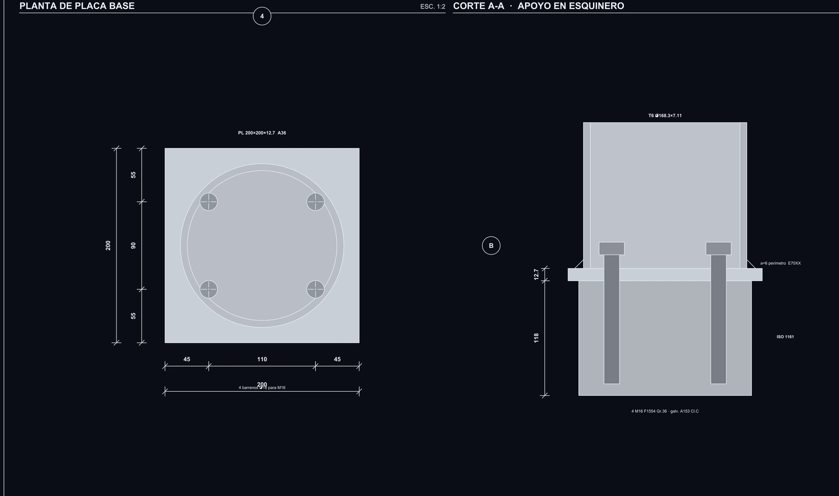
Six of the eight base plates drop just half a meter and land precisely on the ISO 1161 container corner casting—never on the corrugated roof. 200×200×12.7 mm base plate with four galvanized M16 anchor rods.

The remaining two supports belong to Truss 04, which cantilevers past the 40 ft container and steps down to a concrete pedestal via a 2.639 m column. They are not interchangeable, as explicitly warned on the blueprints.

Planta de placa base y corte del apoyo sobre esquinero de contenedor

Fig. 02 — Corner Casting Base Plate · Sheet S-07

Base plate PL 200×200×12.7 A36 steel, four Ø18 mm holes for M16 F1554 Gr.36 galvanized anchors (ASTM A153 Cl.C), 6mm perimeter fillet weld with E70XX electrodes.

04 Governing Environmental Load

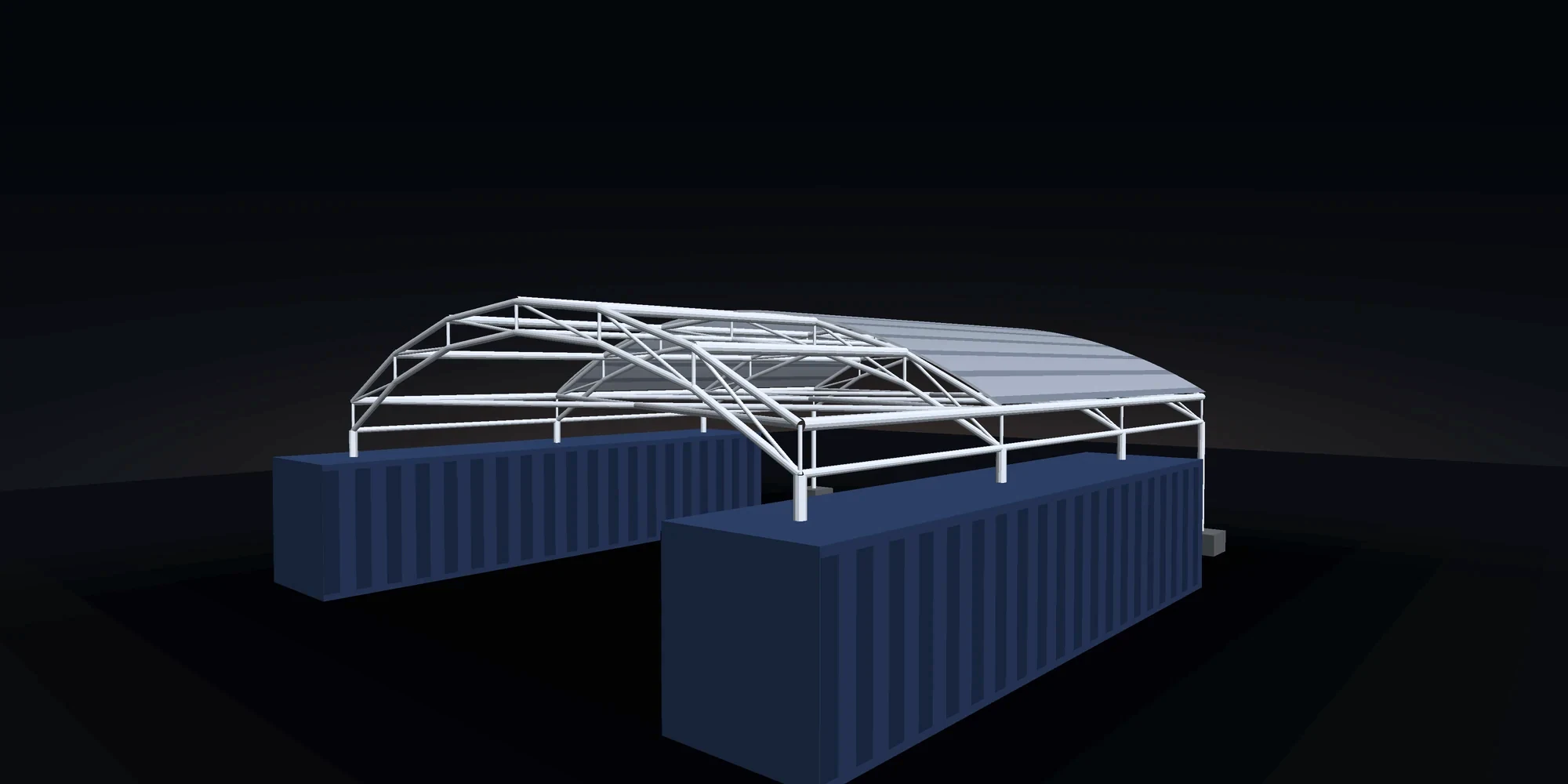
Vista isométrica del conjunto con la cubierta parcialmente montada

Fig. 03 — Overall Assembly · Rendered from Analysis Model

Generado con la geometría del modelo de análisis: 64 nodos y 144 barras, cada tubo con su diámetro de entrega.

Here, wind does not push down. It pulls up.

A lightweight curved canopy in a coastal environment experiences aerodynamic suction. The governing load combination for foundation anchorage is ASD 0.6D+0.6W: dead load is factored to 60% while wind produces massive uplift.

Max point uplift tension
27.78 kN
Total uplift per container
109.26 kN
Max downward compression
32.87 kN

La distinción no es cosmética. La tracción puntual dimensiona el ancla y la placa de cada apoyo; la suma del costado dimensiona la viga de reparto sobre la caja. Confundirlas fue un error de la revisión anterior, y quedó anotado en el modelo para que no se repita.

05 157 Engineered Joints

Zero joints overstressed. And we know the highest-stressed node.

Every joint was computed individually: 137 direct welded tubular connections and 20 bolted end-plate connections. Median ratio is 0.115—the structure possesses substantial safety margins.

The governing joint verifies at 0.829 (Node 33). Zero joints above 1.0.

06 Shop & Fabrication Drawings

We don't just deliver a model. We deliver fabrication cuts.

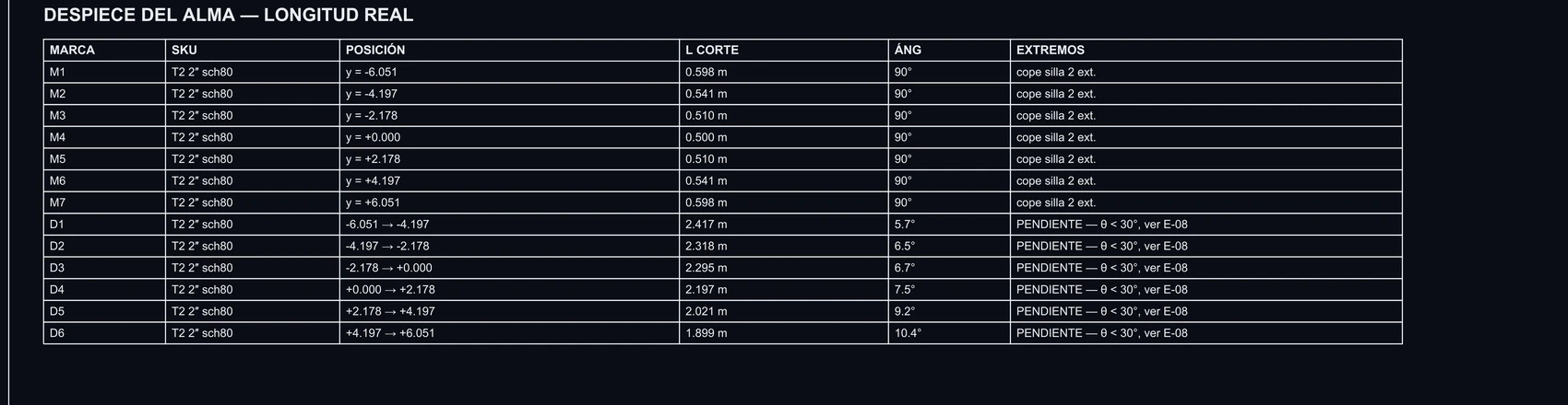
Tabla de despiece del alma con marca, posición, longitud de corte y ángulo

Fig. 04 — Web Lacing Cut Schedule · True Lengths

Each strut and diagonal with its mark, axis station, true cut length to the millimeter, and end bevel profile.
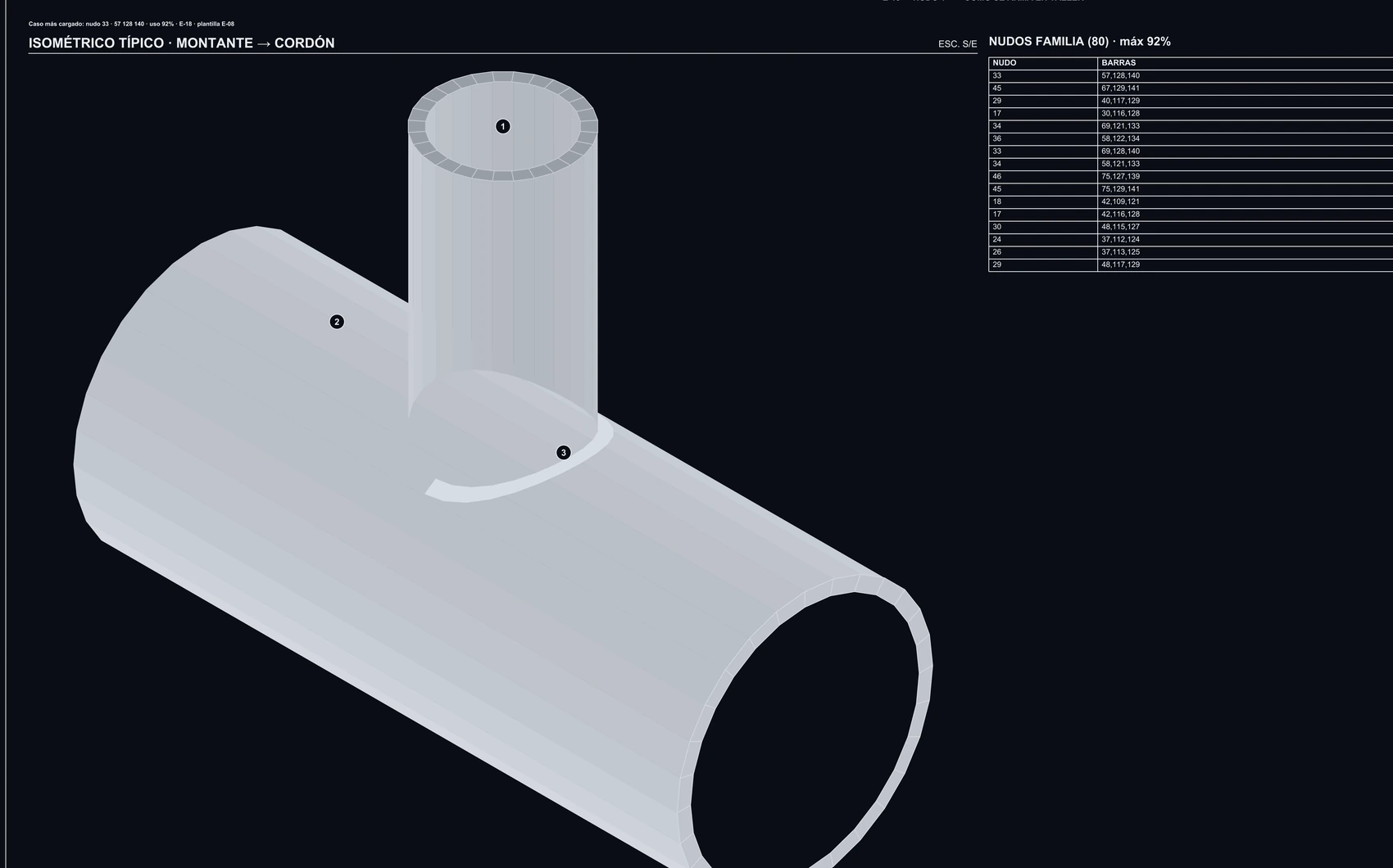
Ficha de nudo tubular tipo T con geometría de corte

Fig. 05 — Typical Tubular Joint Detail

6 dedicated shop fabrication sheets accompany the 23 structural sheets: T-joints, K-joints, field splices, column headers, and non-standard connection details.

07 Scope & Technical Exclusions

Written clearly on our own drawings.

An honest scope of work is stated on the drawing sheets, not in a conversation nobody remembers.

From analysis model to fabrication cuts,
without errors.

23 structural drawing sheets, 6 shop fabrication sheets, 33-page calculation package, and 157 individually calculated joints.

Discuss your steel structure